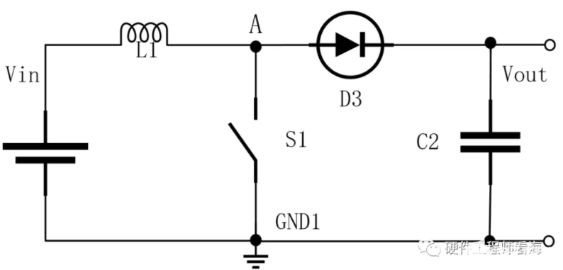
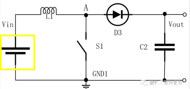
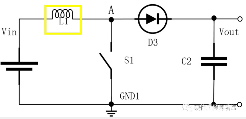
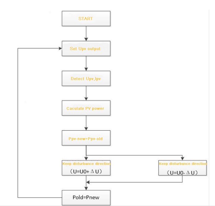
By changing the output voltage of PV ( Boost Circuit achieves this function), and sampling the output voltage and current of PV system in real time, the output power of PV system is calculated, and then compared with the out power of PV system obtained in the previous time. If it is greater, the disturbance direction is correct, and the original direction is maintained; If the power is smaller, it means that the output power of PV system declines, and the output voltage of PV system should be reduced. Such repeated disturbance, observation and comparison make the PV array finally work at the maximum power point.
The specific working process is to detect the open circuit voltage of PV system before the Boost circuit starts working. Generally, about 80% of the open circuit voltage is taken as the tracking voltage. The PV system is working near the maximum power point at this time.
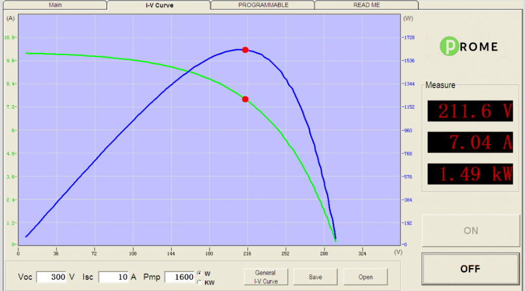
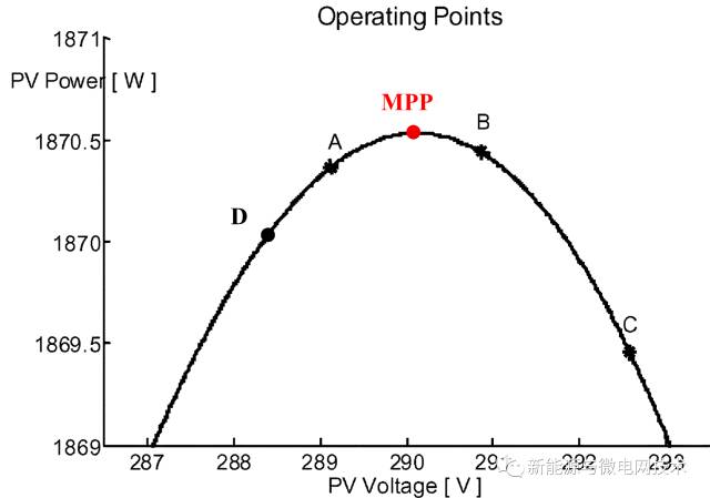
When the open-circuit voltage of the PV system is U0, that is, the output power is P0, select a small variable ΔU, change its working voltage to U1, and the output power of the PV system is P1, compare the magnitudes of P0 and P1, and take ΔP=P1- P0.
When ΔP/ΔU=0, PV system works at the maximum power point; if it is not 0, when ΔP/ΔU>0, the working voltage of the maximum power point should be on the right, maintaining the disturbance direction (U=U0+ΔU) ; When ΔP/ΔU<0, the situation is reversed and the flow direction is changed (U=U0-ΔU).
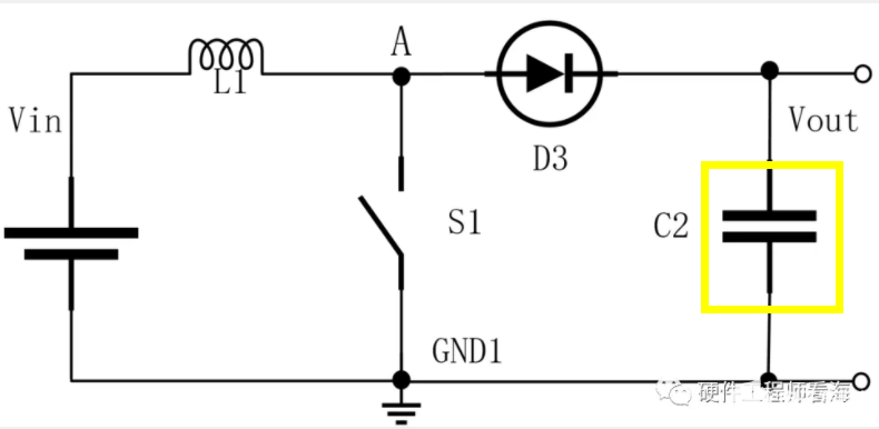
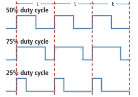
In order to realize the tracking control of the maximum power point, it is necessary to change the output voltage of the PV system by changing the duty cycle of the MOSFET or IGBT, so as to achieve ΔP/ΔU=0, to control its operating point at the maximum power output point. The program flow of the interference observation method is shown in Figure below.